As far back as I can remember, I’ve been a fan of Michigan Football. Whenever I would go to games, I’d get all decked out in Maize and Blue. But at some point late in high school, I decided that wearing a bright yellow hoodie, sweat pants, gloves, hat, shoes and socks just wasn’t quite enough. Sure, I was the most fashionable guy around, but surely there had to be a way for me to show my school spirit even more. So I went down to my basement workshop, printed out some iron-on circuit boards, mixed up some chemicals, got my Radioshack soldering iron hot and made this:
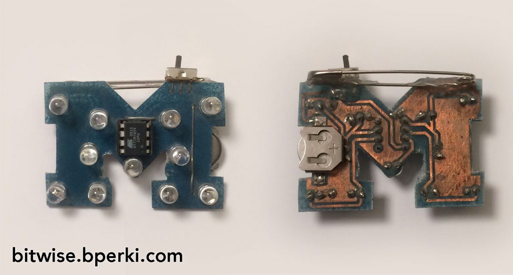
A blue “Block M” pin, with blinking yellow LEDs. Sure, it’s got some shortcomings and oversights (current limiting resistors? We don’t need no stinkin’ current limiting resistors), but I was in high school, so I’ll give it a solid C for effort. Let’s take a quick look at what we’ve got on the board:
- Single sided PCB (with two wire jumpers)
- 12mm battery
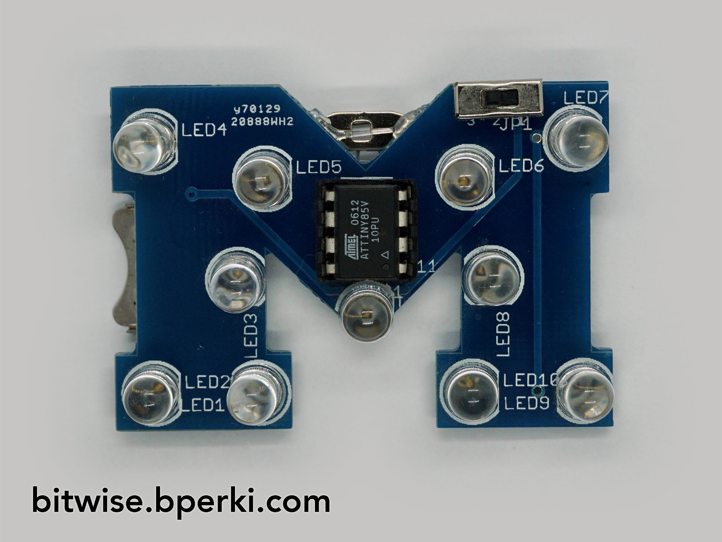
- 11x 5MM yellow LEDs
- ATTiny85 8-pin microcontroller
- Power switch
- Safety pin (not only does the hot glue keep it in place, it also prevents it from shorting the power switch, wow!)
“But wait!”, I hear you saying. “There are 11 LEDs, and your microchip only has 8 pins, how are you controlling all the LEDs separately?” Oh, I already thought of that and it’s simple… I’m not. I simply created 5 groups of LEDs and controlled each group with an IO pin. That leaves two pins for power and the other pin (reset) is left floating — quite literally, the copper pad came off when I drilled the hole, so it’s not even soldered. As far as the blinking goes, it had several different patterns and used the non-volatile EEPROM to switch to the next pattern each time you turned it off and on. All things considered, I’m amazed that this circuit worked as well as it did; the battery lasted long enough to blink for multiple games before needing to be changed and even now, nearly 10 years later, it still works.
A couple of years after making this, when I was in college, I discovered the miracle of $10 PCBs and decided I should order a couple of boards to make them more “professional”. I added a second battery holder in parallel to double the run-time and submitted my Eagle board file to iTead. Unfortunately, at that point, my experience in PCB fabrication was primarily limited to etching boards at home, so I ended up with white labels and part names all over the front of the board. Regardless, I was just excited to have something manufactured, so I didn’t particularly care.
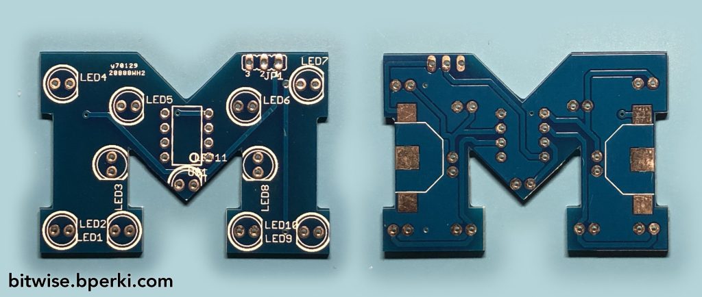
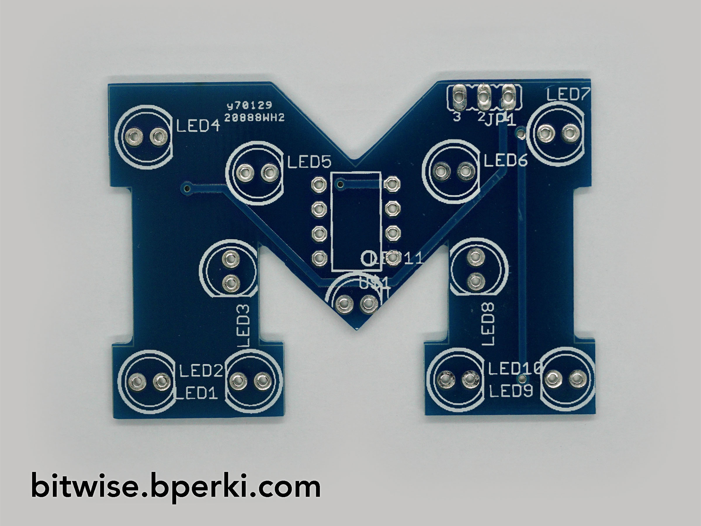
This one has actual soldermask on it, a surface finish that won’t oxidize, and twice the battery capacity! Good work, Freshman-Ben. The improvements stop there, though. Same 5 groups of LEDs, same code, and a more visually-cluttered front.
For the next several years I wore these occasionally, but mostly just let them gather dust and thought of them fondly as a fun little side project I made when I was younger. In early 2018, I was on a circuit board streak that had me ordering new PCBs every month or so for a handful of projects and I thought to myself “You’ve learned a ton since you built these, why not give it another go and see what you can come up with?”
My list of must haves included:
- No unnecessary silkscreen on the front
- Surface mount components
- Visual flare with either ENIG or yellow silkscreen, if possible
- More “badge-friendly” design
- Individually addressable LEDs
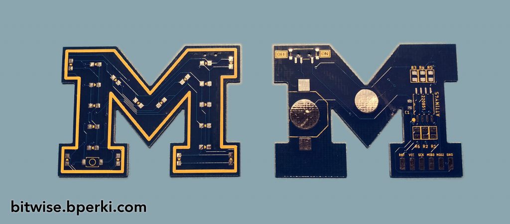
I searched the web for a PCB manufacturer that would make small quantities of blue soldermask with yellow silkscreen and stumbled across AllPCB. I’ll talk more about them when I write a post comparing all the manufacturers I’ve used, but they were willing to use the unique color combination I wanted for a very reasonable price, not to mention they included free DHL shipping. I got to work on a new design and a couple of hours later placed the order. I’ll admit that I was a bit hasty on the layout because I misread the AllPCB website and thought the free-shipping was a temporary sale. In my haste, I forgot to put my signature and design date on the back of the PCB. Darn.
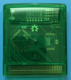
Five days later (seriously, PCB manufacturing is unbelievable these days), the PCBs showed up and I ripped the box open:
Whoops. This was originally supposed to include pictures of the assembled pin, a code overview, power optimization and a video, but I’ve rambled far too long already. I’ll end this post here and have another one with all those exciting details soon.
One thought on “Revisiting One Of My First Projects – Now With More LEDs! (“Block M” Pin Update #1)”