In my previous post, I talked about the motivation behind my updated “Block M” LED pin and compared it to the previous iterations to show how far it’s progressed since I designed the first one nearly 10 years ago. Today I’m going to wrap up by going over the electronics, code and power optimizations.


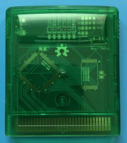
One of the goals of this project was to keep the component count and cost as low as possible. With that in mind, let’s look at what’s on the PCB:
- 12mm battery
- 20x 0805 yellow LEDs
- ATTiny45 8-pin microcontroller
- Power switch
- Push button
- 5x 0805 (current limiting) resistors, 330Ohm
- 1x 0805 (pull up) resistor, 5.6kOhm
- 1x 0805 bypass capacitor, 0.1uF
- Tie tack pin
The ATTiny45 is the most expensive component on the board, but I intentionally kept the code below 2KB, so that an ATTiny25 can be used instead, which is usually a couple cents cheaper. In my case, I found a sale on ATTiny45s that brought the price down well below the 25 variant.
For code simplicity, I decided to program it in the Arduino environment. There are already plenty of tutorials on how to set it up to program ATTinys, so I won’t repeat that here. However, if anyone was interested in re-creating this project without using the Arduino environment, it would be incredibly simple. The only Arduino library I used was EEPROM, and there’s a #define at the top of the file to disable use of EEPROM entirely (although, you’ll be limited to a single pattern if you do this).
The previous versions of this grouped LEDs together to deal with the limit of 5 IO pins on the ATTiny45, but for this version, I wanted to be able to individually control each LED, so I turned to a method called Charlieplexing. This allows me to control up to 20 LEDs individually using the 5 IO pins, with the limitation that only a single LED can be on at any time. Fortunately, our brains can be tricked easily and by cycling through the LEDs rapidly, we can create the illusion of illuminating any combination.
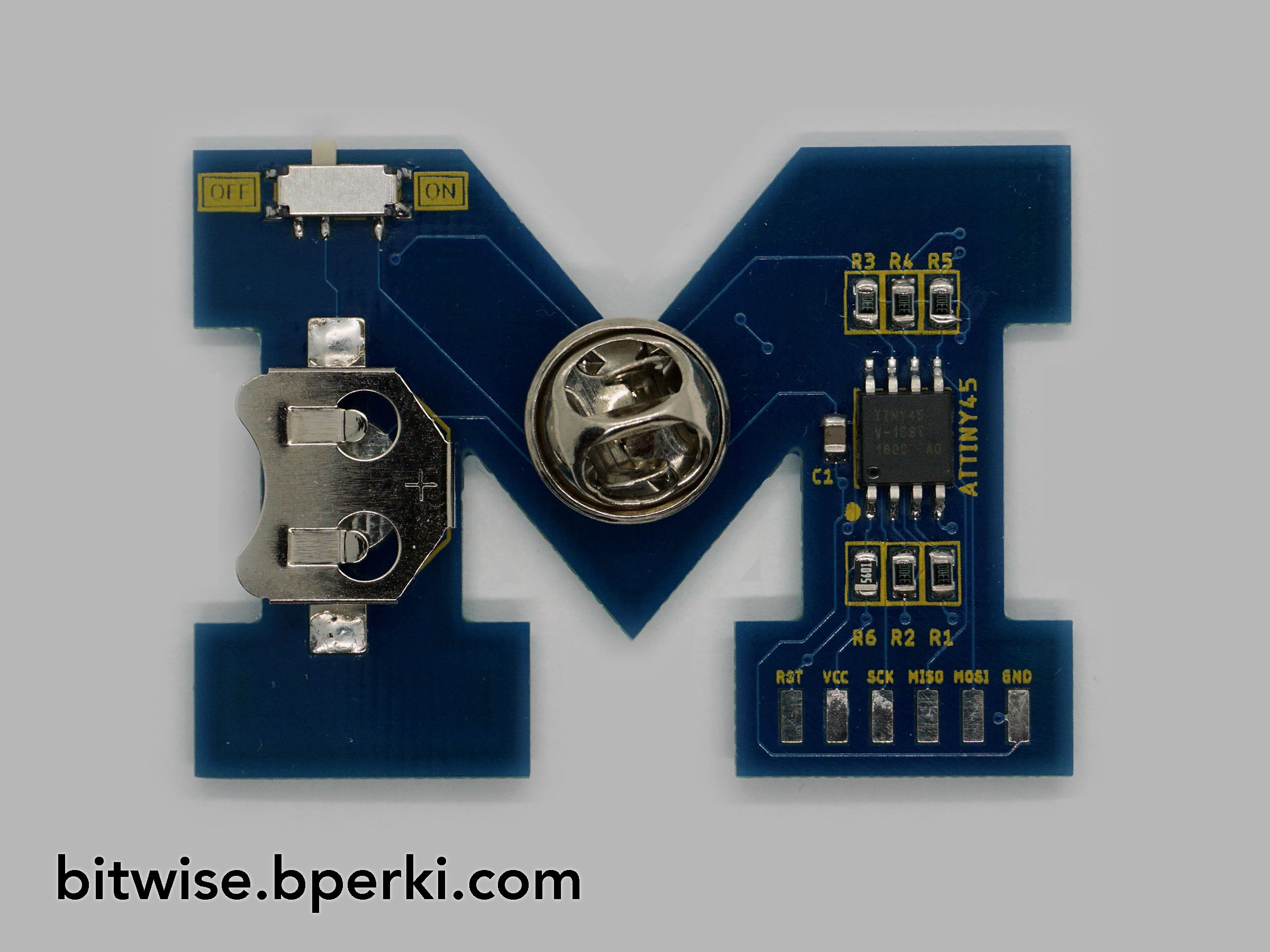
The previous version displayed a different pattern every time it powered on, but that was a major annoyance since there was no way to display the same pattern twice in a row without cycling through all of them. For this version, I solved that problem by adding a reset button in addition to the power switch. At first glance, this doesn’t seem like it would do much, either you’re cutting the power with a switch or by resetting the device — the code can’t tell the difference, right? Actually, most microcontroller will have a way to tell you what the cause of a reset was, so it’s possible to tell the difference between flipping the switch and pressing the button. For the ATTiny series, this is done with the MCUSR (MCU Status Register). There are four different ways to reset this chip; power-on reset, external reset, watchdog timer reset and brown-out reset. I won’t go into the differences here, but more information is available in section 8.2 of the datasheet. Alternatively, it is possible to disable the external reset functionality and use that pin as another input, but that forces you to use a high voltage programmer to re-flash the chip, so for usability reasons I opted not to go down that route.
The other major difference between this and the previous versions is the use of surface mount components. These provide a much cleaner appearance since they can be hidden on the back and don’t need holes drilled through the board. However, through hole microchips are much easier to program since they can be plugged into a breadboard or socket before soldering into the circuit. Since that’s not as easy for this chip, I added programming headers to the back side of the board, but there are some caveats. Firstly, I didn’t want a programming header sticking off the bottom of the pin all the time, so I just press a right-angle 0.1″ header against the pads to program without soldering. Secondly, and much more importantly, the programming lines are shared with the LEDs, which means that some of the voltage from the programmer is going to get dropped across the LEDs, and if that voltage drop is high enough, the microcontroller won’t recognize the correct signals and won’t be able to be programmed. There are two ways to work around this, you can either program the microcontroller before attaching the LEDs, which is the best option if you don’t want modify the code. If you want to use this as a development board, though, you’ll need to use high value resistors (>2kOhm). This will make the LEDs very dim, but it will allow you to reprogram it without removing any components.
Ok, enough talk — let’s see it in action! Below is a video showing a few patterns from the old version compared to the new, updated version of the same patterns:
It should be noted that the old version used highly directional LEDs, which are very bright if you’re looking straight at them, but are much dimmer if you’re looking at them from an angle. The new version uses LEDs with a much wider viewing angle, which means they appear slightly less bright when looking straight on, but are visible from the side as well.
Ok, now that we’ve seen a few of the patterns, let’s take a look at the code that’s making it work. Since I built this in the Arduino environment, we’re going to have the same setup() and loop() functions that will be familiar to anyone who’s used Arduino before. Let’s take a look:
void setup() {
  // Determine if we should update the random seed 'a'.
  bool updateA = false;
  // Determine if the button was pressed (external reset).
  if(MCUSR & (1 << EXTRF)) {
    buttonPressed = 1;
  }
  // Reset the status register.
  MCUSR = 0;
#if USE_EEPROM
  // Read the saved pattern index and random seed 'a'.
  patternIndex = EEPROM.read(EEPROM_ADDR_PATTERN);
  a = EEPROM.read(EEPROM_ADDR_RAND_A);
  // If the button was pressed, increment pattern.
  if(buttonPressed || patternIndex >= NUM_PATTERNS) {
    patternIndex += 1;
    // If we exceeded the number of available patterns...
    if(patternIndex >= NUM_PATTERNS) {
      patternIndex = 0;
      // Increment random seed
      a++;
      updateA = true;
    }
    EEPROM.write(EEPROM_ADDR_PATTERN, patternIndex);
  }
  // Make sure 'a' stays in the acceptable range
  if(a > MAX_RAND_A || a < MIN_RAND_A) {
    a = MIN_RAND_A;
    updateA = true;
  }
  if(updateA) {
    EEPROM.write(EEPROM_ADDR_RAND_A, a);
  }
#else
  patternIndex = 0;
#endif
  // Power saving functions.
  ACSR |= _BV(ACD); // Disable ADC.
  ADCSRA &= ~_BV(ADEN); // Disable ADC.
  // Unlock watchdog to allow changes (see datasheet section 8.5.2).
  WDTCR |= (_BV(WDCE) | _BV(WDE));
  // Disable watchdog.
  WDTCR &= ~_BV(WDE);
  WDTCR &= ~_BV(WDIE);
  // Shut down all timers (none are used).
  PRR |= _BV(PRTIM0) | _BV(PRTIM1) | _BV(PRUSI) | _BV(PRADC);
}
I know it looks like a lot, but it’s actually quite simple. Looking at it step-by-step, all it does is:
- Determine if the button was pressed or not
- Read the last displayed pattern and random seed from EEPROM
- If the button was pressed, update the pattern
- If we reach the end of the patterns, go back to the first one and increment the random seed
- Disable some features on the microcontroller to save power
That’s IT. Once that’s done, the code enters the loop() function:
void loop() {
  static uint8_t leds[NUM_LEDS] = {0};
  switch(patternIndex) {
    case 0:
      patternFadingBlink();
      break;
    case 1:
      patternChase();
      break;
    case 2:
      patternLoop();
      break;
    case 3:
      patternWipe();
      break;
    case 4:
      patternFlash();
      break;
    case 5:
      patternFade();
      break;
    case 6:
      patternBoomIn(leds);
      patternBoomOut(leds);
      break;
    default:
      delayCycles(MAX_DELAY);
      break;
  }
}
This one is even easier. First we create a static array the same length as the number of LEDs we have. Using the static keyword means that this variable will only be set when it’s created, but it won’t be reset back to its initial value when the code hits that line again, so it’s value will persist each time we loop. This is only used by the “boom” pattern, since it calls two different functions that need to share state. After we create that variable, the code enters a function based on which pattern we want to display, and then it loops. Nothing to it.
Finally, we’ll look at one of the pattern functions to see how it works:
/*
 * Function:  patternLoop
 * --------------------
 * LEDs fill up one at a time before unfilling one at a time
 * Should be called in a loop.
 */
void patternLoop() {
  uint32_t bitmap = 0;
  for(uint8_t j = 0; j <= NUM_LEDS * 2; j++) {
    for(uint16_t i = 0; i < 50; i++) {
      drawBitmap(bitmap);
    }
    bitmap = bitmap << 1;
    if(j <= NUM_LEDS) {
      bitmap |= 1;
    }
  }
}
This function turns the LEDs on one at a time starting from the bottom-left and once they’re all on, turns them off one at a time in the same order. To make this work, we use a helper function called drawBitmap, that handles all of the Charlieplexing logic for us. All we need to do is tell it which LEDs to light up by setting those bits to 1. For example, if we had 8 LEDs, the bitmap 00000001 would light up only the first LED. 11110000 would light up LEDs 5, 6, 7, and 8 while leaving 1, 2, 3, and 4 off. In this case, we have 20 LEDs, so we need a 32-bit integer to hold all the values, but the idea is the same. To create the effect, we loop over twice the number of LEDs we have and shift the bitmap one bit to the left each time. If we’re in the first half of the loop, we also set the newly shifted-in bit to be a one. Assuming we only had four LEDs, that would look like this:
(Start   Shift   Add 1)
 0000 -> 0000 -> 0001
 0001 -> 0010 -> 0011
 0011 -> 0110 -> 0111
 0111 -> 1110 -> 1111
(Start   Shift)
 1111 -> 1110
 1110 -> 1100
 1100 -> 1000
 1000 -> 0000
(Repeat)
Some of the functions get a little more complicated than this, but they’re all available on Github and I encourage you to check them out if you’re interested.
Finally! We’ve looked at the electronics and the code, all that’s left is to take a look at the power draw. This project uses a single 12mm battery and I want it to last at least the duration of two football games (~4 hours each), but preferably longer. There are a few different sizes of 12mm batteries: 1212 (1.2mm thick), 1216 (1.6mm thick), 1220 (2.0mm thick) and 1225 (2.5mm thick). The capacity increases roughly linearly with the thickness, so we’ll use the 1225 since it provides the most capacity. Looking at a datasheet for our battery, it claims 48mAh of capacity, but looking closer, we can see that number only applies to very small loads. As the load increases, the capacity of the battery will decrease. This means that we’ll need to pick the best trade-off between brightness and run-time by adjusting the resistors R1 – R5. Since we’re Charlieplexing the LEDs, at most one will ever be illuminated at a time, so we can use that as an upper bound of our current consumption. If we want the LED to draw around 2mA, we can use Ohm’s law to compute the resistance (R = V/I). Given the battery is 3V and the LED has a forward voltage of 1.8V, that leaves 1.2V to be dissipated by the resistors (remember that the current passes through two resistors for any LED).
1.2V / 0.002A = 600Ohm
So we know that we should have roughly 600Ohms of total resistance, or 300Ohms for each R1 to R5 to achieve 2mA per LED. I decided to use 330Ohm resistors since that’s a common value. This should give about 1.8mA for the LEDs, plus the current of the microcontroller.
Of course, there are a lot of other factors that will come into play here, like the internal resistance of the LEDs, since they’re being pulsed rapidly, so it’s important to actually measure the current. My multimeter wasn’t up to the task of measuring such small currents, so I took a note from Jay Carlson and used an STK board I had laying around with Simplicity Studio to measure the current. I followed this guide to hook up my circuit and within a few minutes, I was getting current measurements with nA-range accuracy, awesome!
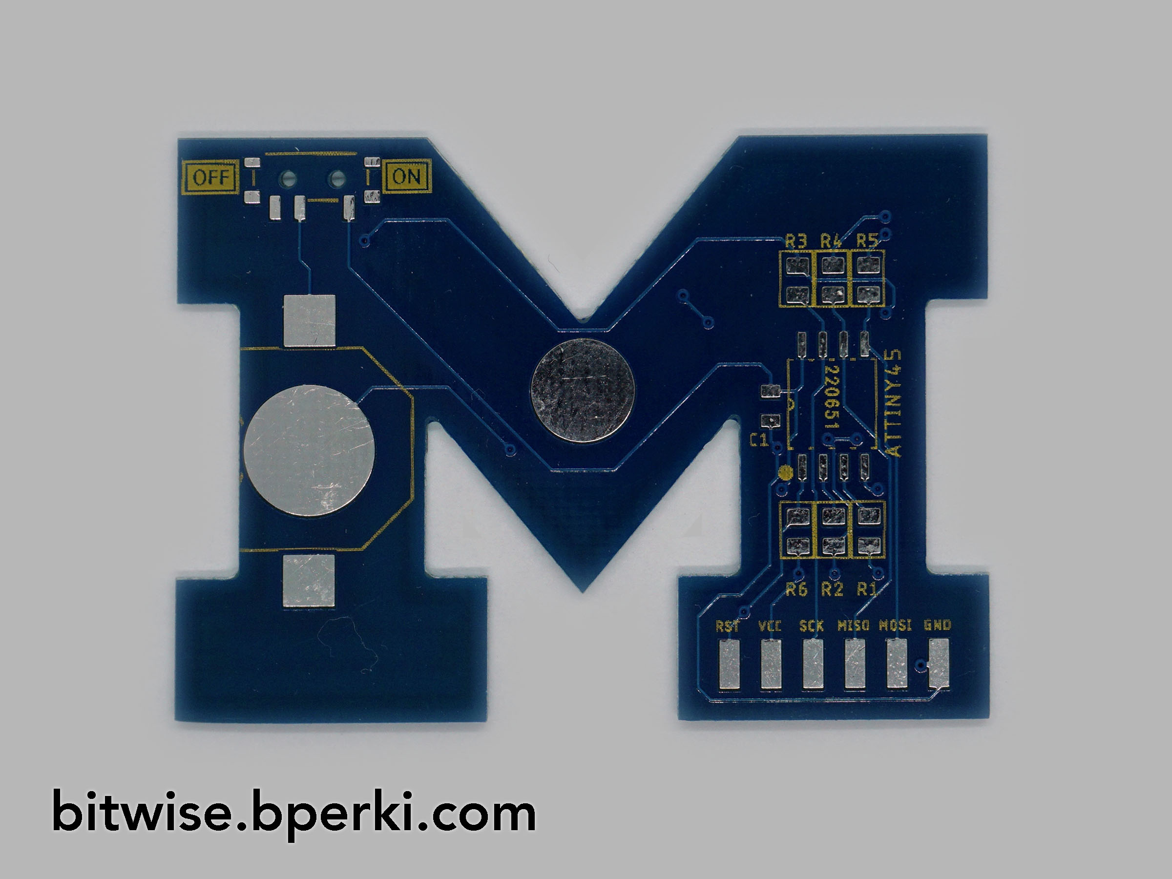
The first thing I wanted to do was to compare the effectiveness of the power-saving features I had added to my setup() function. By disabling the ADC, watchdog, brownout and all timers on my ATTiny, I knew I would be saving power, but I wasn’t sure how much. A quick check confirmed that I was saving about 400uA, a 35% reduction in MCU current:
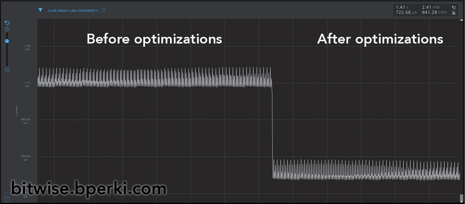
Now let’s add the LEDs to the mix. Here’s a capture of the ‘Flash’ pattern (all LEDs on, then all LEDs off):
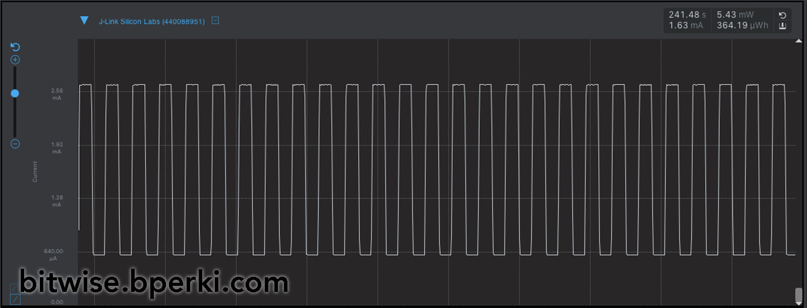
We can see that the current ranges from ~640uA to ~2.5mA depending on if the LEDs are on or off, giving an LED current of about 1.86mA. This lines up almost exactly with what we predicted. This pattern has an average current draw of 1.63mA, if we were able to get the full 48mAh out of the battery, that would give us a run-time of nearly 30 hours. Of course, the battery capacity will likely be much lower, maybe even as little as half of that, but that still far exceeds the 8 hour minimum I was aiming for. I may even drop the resistor values slightly to get extra brightness after I see how well it performs in practice.
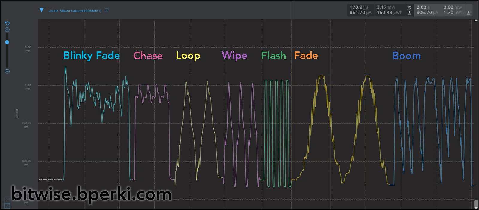
Below is a video of each of the patterns with the current consumption plotted. It’s important to note that this is my development board, so it has much higher resistor values and therefore lower current draw, but you can still get a sense of how much power each will draw relative to one another, with the peak current being about 2.5mA and the minimum being about .625mA:
Here’s a plot of each of the different patterns all in one image:
There you have it. Nearly 10 years after my original idea, I finally feel like I have something I can be proud of. All of the code and Eagle files are available on Github, feel free to download them and modify them however you’d like. If you do create a similar project from my files, be sure to send me a picture, I’d love to see it!
One thought on ““Block M” Pin Update #2 – Software, Power and Videos”