I’m a big fan of the old (and recently-rebooted) TV show Mystery Science Theater 3000. If you’re not familiar with the show – where have you been for the past 30 years? – it’s set in space and features Joel (or Mike or Jonah, depending on the season) watching and making fun of B C movies and his robot friends. Just before the commercial breaks in the first few seasons, they showed scenes from a miniature, futuristic cityscape with an iconic Mystery Science Theater 3000 billboard.

Ever since I was young, I’ve wanted to make my own MST3K billboard. Despite the fact that I probably could have built the electronics at any point in the past 15 years, it wasn’t until recently that 3D printing made it possible to easily create a plastic billboard-shaped frame. Now that I’ve got a my own 3D printer, it was finally time to get off my butt and start working on it… Well actually, I stayed sitting for the pretty much the entire time.
The Circuit Board
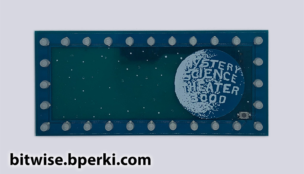
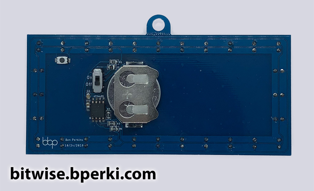
The design is simple enough, it can be fabricated on a single circuit board with a 3D-printed enclosure. The blinking lights are just 3mm LEDs and the logo can be printed directly onto the silkscreen layer of the circuit board. In order to create the lighter, almost backlit look of the original, I opted for a thin PCB and omitted the copper in the star-field. I also decided to use a combination of silkscreen and drill holes to create stars that would be bright whether it’s illuminated from the front or the back. I used the 11×5 grid of LEDs as a guide to approximate the dimensions of the billboard – although I admittedly pushed them a little closer together in order to keep the PCB under 10cm wide, which drastically reduces the cost. Many PCB fab houses will give you 10 copies of this design for $5, plus shipping.
The silkscreen on modern circuit boards is high enough resolution to create very sharp designs, but those designs will only look as good as the source image. The process uses a single color of ink (white in this case), so an image needs to be reduced to 1-bit color before it can be added to the PCB. Most images that look black and white actually have lots of grey (and sometime even color) around the edges to create a smoother look on computer and phone screens. In order to convert an image from grey-scale to 1-bit, a process called dithering is used where every shade of grey is approximated using small dots of either black or white. After this is done, a little bit of manual adjustment is necessary to make it look just right.
In the original design, half of the LEDs are on while the others are off and then they alternate, back and forth. This makes for a very simple design, since we can cluster all of the LEDs into two groups and simply use a single IO pin to control the groups one at a time. Doing this removes the ability to control the LEDs individually, but it leads to a much simpler circuit, which is important since I don’t want any visible traces.
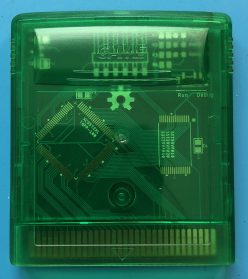
I tried to keep most of the components hidden behind the moon so they wouldn’t create a silhouette on the front side, but the programming header didn’t fit and the switches I had handy needed guide holes drilled through the PCB, which I didn’t want messing with the moon design. It looked alright for a first attempt, but I knew I was going to need to tweak one or two things before I was truly happy with it.
| I didn’t like that… | So I… |
|---|---|
| …the silkscreen wasn’t sharp enough to see the design clearly | …touched up the original image to make sure there was more clearance between each of the letters (fourth step in the above animation) |
| …the components and traces not behind the moon caused a silhouette on the front | …moved all the components behind the moon |
| …the mounting holes for the switch prevented me from putting it behind the moon | …managed to find a small SMT switch with a J-lead package and no guidance holes |
| …the button on the front distracted from the feel of the original | …moved the button to the back side |
| …the long trace connecting the LEDs on the top layer wasn’t connected to the copper rectangle around it | …just connected it to the copper rectangle |
| …some silkscreen stars had drill holes directly through them which ended up looking messier than I anticipated | …separated all the drill-hole stars from the silkscreen stars |
| …the soldermask I left off the back to let more light through ended up looking messy | …added back the soldermask to the whole board |
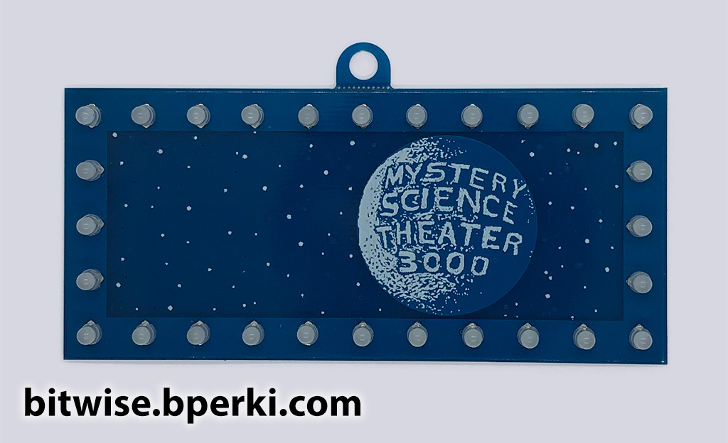
| …the corner LEDs were ever so slightly out of line with the others | …rotated them to be vertical instead of at 45° angles |
| …the moon was too far to the right! How did I miss that?? | …shifted the moon and all the components to the left |
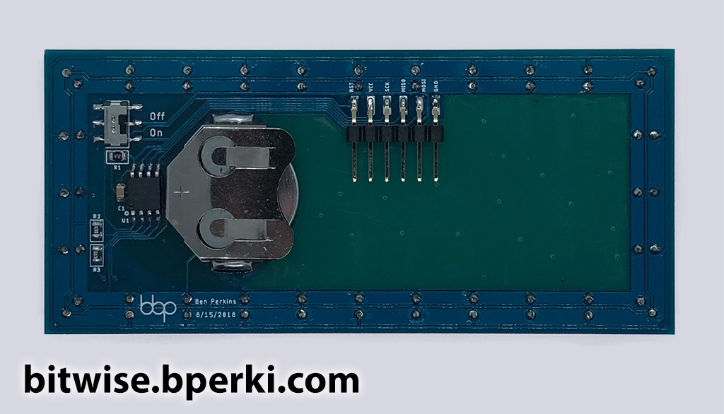
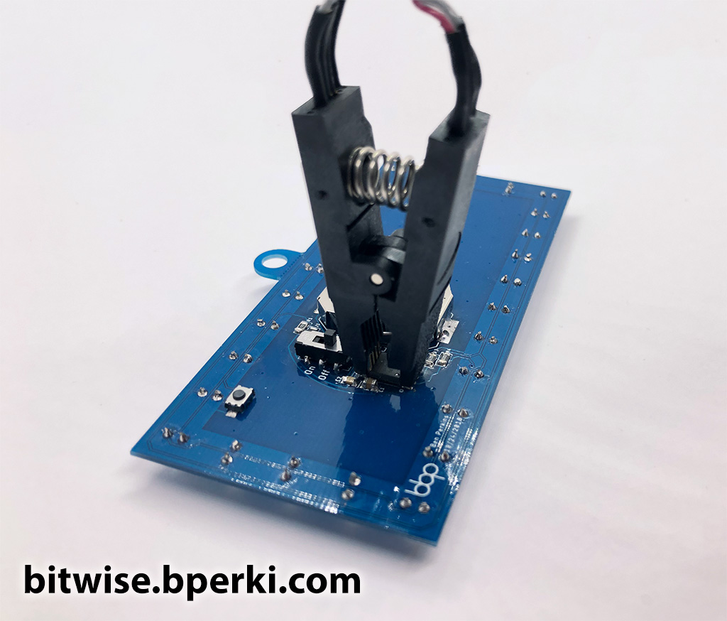
You know, just one or two little tweaks. Also, I didn’t actually put all of the components behind the moon. I wanted the button to be easy to find from the front, so it’s still in the star-field, but I tried to hide it with some strategically placed stars. The other issue is that the 0.1″ programming header wouldn’t fit behind the moon, but I decided that I could just program the ATTiny before soldering it onto the board. Unfortunately, for debugging that wasn’t going to be a viable option, so I searched the web and found some neat clips that allow you to program an SOIC-8 chip directly on the PCB. (If you think I sprung for the $18 clip, you clearly don’t know me… I found similar versions for less than $3 elsewhere. They don’t work great, but they work well enough.) Finally, I also added a tab on the PCB to make it easy to hang as a decoration.

The Software
This project uses an ATTiny45 to blink about 20 LEDs, it runs on a coin-cell battery and has a power switch and a button. No, wait… That’s my last project. Hmm… Am I in a rut? Maybe I’m just doing an excellent job making modular, reusable designs. Yeah, I prefer that explanation. I’m going to gloss over the parts of this project that are the same, so if you’re interested in learning more about developing for an ATTiny in the Arduino environment or measuring current consumption on your projects, check out this post on my Block M pin.
The code has two different modes, each in its own function, and the main loop just calls one after the other:
void loop() {
  pokeMode();
  manualMode();
}
Each function has its own loop, so in order to switch from one mode to another, the mode’s function simply needs to return. In both modes, switching is achieved by holding the button for one second. To keep the code DRY, I handle all of the button logic in a single function that is shared by both modes:
inline bool buttonPressed() {
  // Simply handle the hardware abstraction, so I don't need to remember whether the button is active high or low
  return !digitalRead(BUTTON_PIN);
}

uint8_t getButtonPress() {
  uint32_t firstPressTime = millis();
  if (buttonPressed()) {
    // Don't accept another button press until this one ends
    if (!globalButtonReady) {
      return BTN_NO_PRESS;
    }
    globalButtonReady = false;
    delay(DEBOUNCE_DELAY_MS);
    while (buttonPressed()) {
      if (millis() - firstPressTime > LONG_PRESS_DURATION_MS) {
        return BTN_LONG_PRESS;
      }
    }
    return BTN_SHORT_PRESS;
  }
  // If we got here, the button isn't pressed, so we're ready to read another
  globalButtonReady = true;
  return BTN_NO_PRESS;
}
“Poke mode” waits for a button press, then blinks the LEDs for a few seconds. In order to conserve power, the CPU goes to sleep and utilizes a pin change interrupt to wake up when the button is pressed. In fact, the deep sleep mode uses so little power that, even with the battery removed, the board’s bypass capacitor is able to keep the microchip powered for more than 10 seconds! The datasheet contains all the information needed to configure interrupts and put the CPU to sleep, and while I do recommend getting familiar with the different settings there, I found this tutorial to be very concise and useful in getting things up and running.
In “manual mode”, the LEDs blink indefinitely and pressing the button changes the brightness. Switching back to “poke mode” retains the last brightness value set. This brightness value is also stored in EEPROM so it is saved across power cycles. If you want to learn more, or recreate this project for yourself, the full code is available on GitHub.
The 3D Print
So far, the circuit board looks pretty good on its own, but in order to truly replicate the original, it needs a billboard-shaped enclosure. Fortunately, 3D printing has gotten so ubiquitous that for less than $200 anyone can have their own printer. I personally use the MP Select Mini v2, which is currently $180. There are also plenty of services online that will print parts for you for far less than the cost of your own printer.
I wanted to make sure the design was easy to print, so I ended up creating three separate pieces, all of which can be printed without supports even on a low-end printer like mine. The circuit board slides into a grove in two of the pieces, and they simply snap to the third piece. I used Fusion 360 – which has a free option for non-commercial use – for the design.
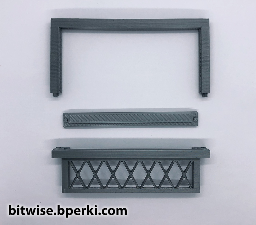

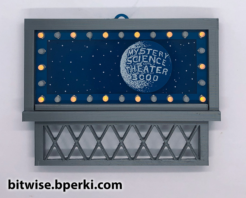
The 3D printed parts actually fit together well enough that I didn’t have to worry about it falling apart – in fact, it fits so tightly that removing the top piece usually snaps off the pegs that hold it into place – but the circuit board wiggled a little bit, especially when pressing the button. To resolve this issue, I just put a small dab of hot glue in each corner on the back. The STL files are available on Thingiverse so you can print your own.

Very cool! I was a big fan of MST3K back in the day as well!
Do you have a JPEG or something of the moon and star field background? I have the O scale billboard already on the way and would love to have the image. Thanks
Here’s a few images you can use, sorry for the delayed response:
https://bitwise.bperki.com/wp-content/uploads/2020/12/Moon-Stars.png
https://bitwise.bperki.com/wp-content/uploads/2020/12/Moon.png
If you happen to know, is this scaled for HO? I am looking to do this as a gift for a new setup my dad is doing.
Sorry for the delayed reply, but this was not designed to be HO scale, so it’s unlikely that it is. The PCB is approximately 100mm wide