Within the last few years, Atmel Microchip has come out with a few new parts in the ATtiny series. They’re quite cheap, even in single quantities, but they’re also very limited in terms of specs. In particular, the ATtiny104 has caught my eye due to having 12 IOs in a fairly small 14-pin SOIC package with a $0.70 price tag for a single piece. Keep in mind though, these parts only have 1kB of flash and 32 bytes of SRAM. Hackaday did a write-up when the 102/104 series was first released and they were “scratching our heads and asking what this chip is good for”. With that glowing endorsement, I rushed over to Digikey and bought 30 of them, because… You know… I’m sure I’ll figure out something to use them for.
Well the time has come. I’ve got an interesting project in mind for these diminutive chips, so I soldered a chip to a generic breakout PCB and got ready to make an LED blink.
Preparing Your Programmer To Speak TPI
First things first, though. Before we can make an LED blink, we need to know how to program these chips. Unfortunately, they don’t use the ubiquitous ISP programming method that most other AVR parts use, they use something called TPI (Tiny Programming Interface). After a lot of Googling, I still couldn’t find a solid answer about a cheap, functional TPI programmer, but I kept seeing references to the USBasp programmer adding support for it in a “new” firmware. Apparently the firmware in question came out in 2011, but the cheap clones of this device apparently still don’t ship with it. Fortunately, it’s possible to update the firmware on the USBasp devices. (I should mention that while it’s great to have a couple cheap USBasp programmers around, the original creator gets no money from these clones, so I highly recommend making a small donation on the official project website if you use them.) In order to do so, the first thing you’ll need is AVRDUDE, this is the software that communicates with your programmer and actually uploads code to your microchip (or downloads code from it, sets fuses, etc). Installing AVRDUDE is as easy as running brew install avrdude (assuming you have Homebrew installed).
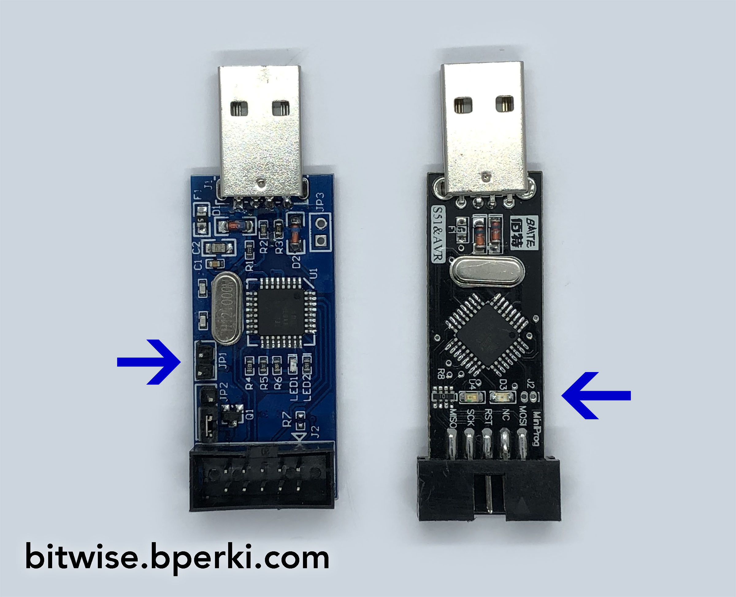
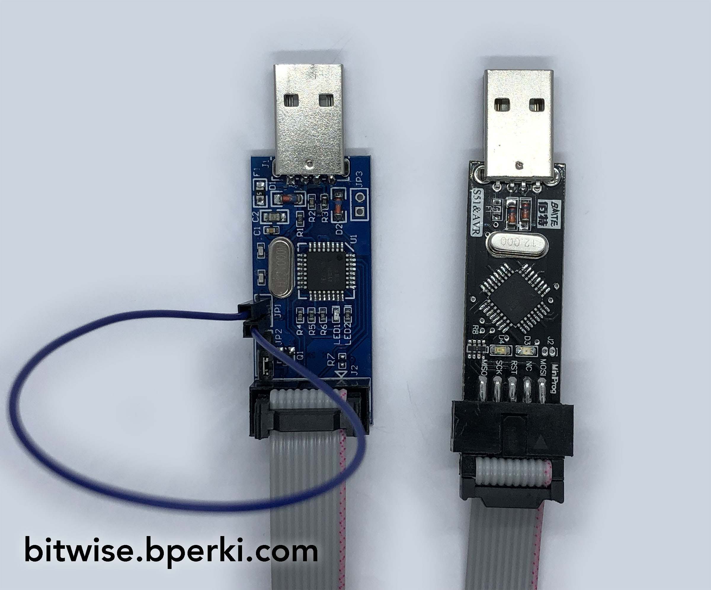
Next, download the 2011 version of the USBasp firwmare, the file is called usbasp.2011-05-28.tar.gz, and unzip that somewhere on your computer. The easiest way to update a USBasp is to use two of them, though using any other ISP programmer will work as well. First, make sure that both programmers are set to the same voltage level. Next plug the first programmer into your computer’s USB port. On the second programmer, find the self-program jumper and connect it – it’s usually labelled J2, but on one of mine it was labelled J1. It will be a two-pin jumper, usually standard 0.1″ spacing, but it may be a solder-jumper on some boards.
Now use the 10-pin ribbon cable that the programmer came with to connect the two devices together. You are now ready to use AVRDUDE to program the USBasp that is not plugged into the computer’s USB port.
First, you may want to back-up the firmware that’s currently running. There are three chips that your USBasp may be using, ATmega8, ATmega48, or ATmega88, look at the chip to figure out which one it is (if you get it wrong, AVRDUDE will refuse to do anything stupid, so it won’t do any harm to the chip). You can do that by running this command from a terminal window (change ‘atmega8’ to ‘atmega48’ or ‘atmega88’ depending on your chip):
avrdude -c usbasp -p atmega8 -U flash:r:usbasp-backup.bin:r
This will save the existing firmware to a file called usbasp-backup.bin in case you want to revert to it later. Next, you’ll want to flash the new firmware to it. The usbasp.2011-05-28.tar.gz file you downloaded earlier has three files in it, inside the bin/firmware directory, one for each of the three microchips. Copy the correct file to the directory that your terminal window is working in and run the following command (again, replacing ‘atmega8’ in both instances, if necessary):
avrdude -c usbasp -p atmega8 -U flash:w:usbasp.atmega8.2011-05-28.hex
Now you can unplug both USBasp devices, reset the self-program jumper on the one you just programmed, and run the whole process again on the other USBasp so they are both updated.
Configuring AVR-GCC To Know About ATtiny104
Now that we have a programmer capable of talking to an ATtiny104, we need a compiler/assembler that’s capable of building our code. If you don’t have avr-gcc install yet, the instructions are here and they essentially boil down to running these commands from your terminal:
xcode-select --install
brew tap osx-cross/avr
brew install avr-gcc
Unfortunately, avr-gcc doesn’t know about the ATtiny102/104 series by default, so you’ll need to do some configuring. First, visit http://packs.download.atmel.com/ and down the Atmel ATtiny Series Device Support. The file-type is ‘.atpack’, but it appears to just be a re-named .zip file. I was able to change the file extension to .zip and then extract the files. Now we need to copy some of these files to the avr-gcc directory so it can use them. The file locations to copy to are based on my installation, which is version 8.2.0 via brew. If yours is different, you will need to slightly alter the file path to reflect your setup. You can also repeat this step with the ATTiny102 files to add support for them as well
| File in ATtiny Device Support pack | Location to Copy File |
| gcc/dev/attiny104/device-specs/specs-attiny104 | /usr/local/lib/avr-gcc/8/gcc/avr/8.2.0/device-specs |
| include/avr/iotn104.h | /usr/local/Cellar/avr-gcc/8.2.0/avr/include/avr |
| gcc/dev/attiny104/avrtiny/crtattiny104.o | /usr/local/Cellar/avr-gcc/8.2.0/avr/lib |
| gcc/dev/attiny104/avrtiny/libattiny104.a | /usr/local/Cellar/avr-gcc/8.2.0/avr/lib/avrtiny |
Configuring AVRDUDE To Know About ATtiny104
In order to modify avrdude to add support for the ATtiny102/104, add this to avrdude.conf (mine was located in /usr/local/Cellar/avrdude/6.3_1/etc):
#------------------------------------------------------------
# ATtiny102
#------------------------------------------------------------

part parent ".reduced_core_tiny"
    id    = "t102";
    desc  = "ATtiny102";
    signature = 0x1e 0x90 0x0C;

    memory "flash"
        size    = 1024;
        offset    = 0x4000;
        page_size = 16;
        blocksize = 128;
    ;
;


#------------------------------------------------------------
# ATtiny104
#------------------------------------------------------------

part parent ".reduced_core_tiny"
    id    = "t104";
    desc  = "ATtiny104";
    signature = 0x1e 0x90 0x0B;

    memory "flash"
        size    = 1024;
        offset    = 0x4000;
        page_size = 16;
        blocksize = 128;
    ;
;
Writing Some Test Code
These microchips are very resource-constrained, so if you’re going to implement a lot of features, you’ll likely want to work in assembly, but let’s start with a simple C program:
#include <avr/io.h>

// Connect an LED to PA5 (pin 7) and then through a resistor to ground
#define LED_PORT PORTA
#define LED_DDR DDRA
#define LED_BIT 5

// The default frequency for these chips is the 1MHz internal oscillator
#define F_CPU 1000000

#include <util/delay.h>


int main(void)
{
    // Set the LED pin to be an output by
    //  setting the correct bit in the DDRA register to 1
    LED_DDR = (1 << LED_BIT);
    // Run the rest of the code forever
    while(1) {
        // Turn the LED on by setting the correct bit in PORTA register to 1
        LED_PORT = (1 << LED_BIT);
        // Wait 1000mS, this function is defined in <util/delay.h> and depends on F_CPU
        _delay_ms(1000);
        // Turn the LED off by setting all pins to 0
        LED_PORT = 0;
        // Wait another second
        _delay_ms(1000);
    }
}
This program will blink an LED on PA5 (pin 7) every two seconds. If you followed along with the above steps, you can save the code above to a file called blink.c and compile it by running:
avr-gcc -Wall -Os -mmcu=attiny104 -o blink.o blink.c
avr-objcopy -j .text -j .data -O ihex blink.o blink.hex
If that succeeds, you will now have a file called blink.hex which can be uploaded to our ATtiny.
Flashing Code To an ATtiny104
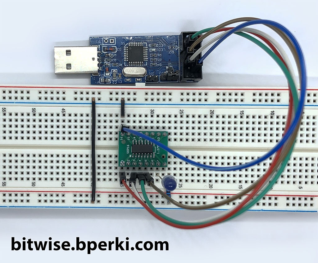
The last thing left to do is hook up our USBasp to the ATtiny and program it. I used some jumpers to connect the USBasp to a breadboard with my ATtiny104. Follow this hookup guide, based on the labels on the USBasp:
| USBasp Pin | ATtiny104 Pin |
| VCC | VCC (pin 1) |
| SCK | TCLK (pin 2) |
| MOSI | TDATA (pin 3) |
| RST | RST (pin 4) |
| GND | GND (pin 14) |
Now we’re ready to upload our program to the ATtiny104 – Finally!
avrdude -c usbasp -p t104 -U flash:w:hello.hex:i
If you’ve added an LED to pin 7 of your ATtiny104, it will now be blinking!
Bonus – Assembly Code
In case you’re interested in how to use assembly code with avr-gcc, it’s pretty simple. Here’s a sample program that doesn’t do much, it just turns on PA5 (pin 7) forever:
#include <avr/io.h>

main:
    ldi r16,0b00100000
  ; Set PA5 to an output
    out DDRA,r16
  ; Set PA5 HIGH
    out PORTA,r16
loop:
  ; Loop forever
    rjmp loop
To assemble this code, save it as test.S and run the following command:
avr-gcc -Wall -Os -nostartfiles -mmcu=attiny104 test.S -o test.o
avr-objcopy -j .text -j .data -O ihex test.o test.hex
Now you can follow the same step to program it to your ATtiny104:
avrdude -c usbasp -p t104 -U flash:w:test.hex:i
Thanks for the great article! I’ll definitely be coming back for more.
Beaut post! Really appreciate the effort you’ve put in.
You’re so awesome! I don’t believe I have read a single thing like that before. So great to find someone with some original thoughts on this topic. Really.. thank you for starting this up. This website is something that is needed on the internet, someone with a little originality!
I appreciate you sharing this blog post. Thanks Again. Cool.